|
|
SXR tomography - electric layout |

| Home | Description | Electronic layout | User manual | Manuale | Info | Images | Results | History | Logbooks | Bibliography | Links |
| Description | ||||||||||||||||||||||||||||||||||||||||||||||||||||||||||||||||||||||||||||||||||||||||||||
|
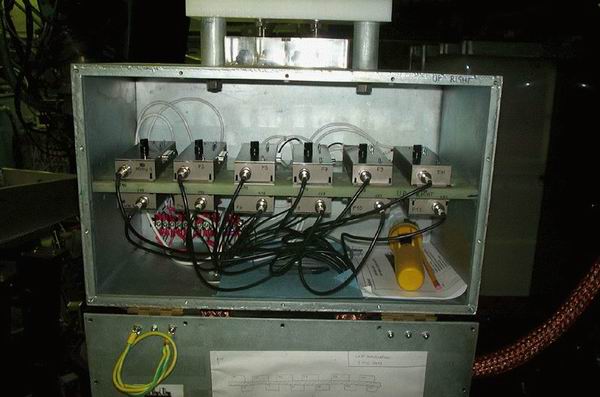
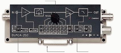
The currents from the diodes are amplified by a set of current-to-voltage transimpedance amplifiers. The SXR1 probe used 12 Femto DLPCA-200 amplifiers (variable gains); see figure1; the box which contains the Femto had to be closed during experiments, and left open during the night, manteinance, or when the data measured by the probes are not important (it gets hot inside, otherwise). The SXR2 probe instead used 12 amplifiers built in the electronic lab of MST, see figure2; these were borrowed from the HSX experiment. The amplifiers were numbered and referred to as Femto1, Femto2, or HSX1, HSX2 etc. The power supplies of the amplifiers were floating, but the shielding of the cables that went from the diagnostic to the amplifiers were grounded to MST.
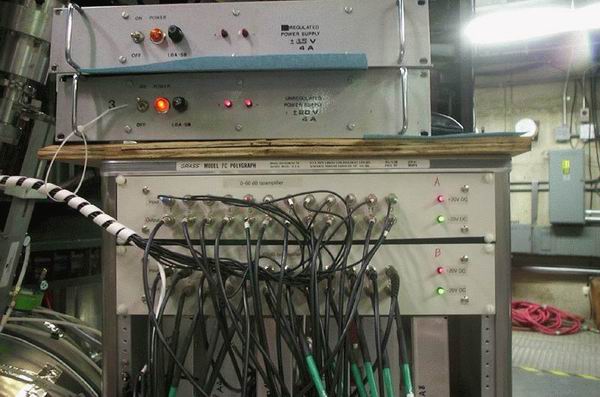
The outputs of the amplifiers were then sent to 24 iso-amplifiers (figure3) and then to the digitizers (Joerger TR612). The iso-amplifiers had also floating power supplies; the cables from these amplifiers to the digitizers were grounded on the CAMAC side (the iso-amplifiers were installed just to ground the cables before and after the amplifiers in different point, that is, before to MST and after to the CAMAC).
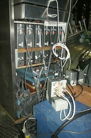
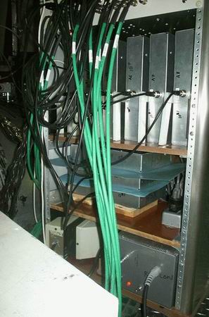
The Femto amplifiers had a single power supply, isolated from the MST ground, and positioned at the base of the rack containing the HSX amplifiers (see figure4). Each HSX amplifier had its own power supply (except two modules, that have a common power supply), all isolated from MST ground (using two isolated transformers, one in the base of the rack of the HSX modules, and another near the rack, see figure5). Finally, the iso-amplifiers were powered with isolated power supplies.
|
||||||||||||||||||||||||||||||||||||||||||||||||||||||||||||||||||||||||||||||||||||||||||||
| To change the gain of the amplifiers | ||||||||||||||||||||||||||||||||||||||||||||||||||||||||||||||||||||||||||||||||||||||||||||
|
The L/H switch selects a factor of 1 or 100, respectively, so, for a certain position of the knob, the total gain is 1x10^8 when the switch selects L (low noise), 100x10^8 when the swith is in the H (high bandwidth) position. For the HSX amplifiers one has to open it and add/change a resistor. The amplifier has to be switched off, removed from the rack, and brought to the electronic lab. Then reinstall the module in the same position, using the same cables as before. These modules have been changed often, so it is possible that a certain gain was already used: in this case the corresponding resistor can be found taped on the amplifier. It is important to use the same resistor because these amplifiers have been calibrated, both in amplitude and frequency. Ask Mikhail for any question. The values of the resistor to be added can be found in the following table:
The present (17 july 2002) layout is described in the following Word files, one for each SXR probe. This layout is valid for 400kA discharges, sustained or not, without PPCD. Other settings, for different types of plasma, are reported in the following table; the numbers are the transimpedance, and so 7=1x10^7, 8=1x10^8, and so on). These values are valid for both the SXR probe, except the last column that is valid ONLY for SXR1 rotated 90 degree (in order to have the lines of sight toroidally):
Each time something is changed (amplifier gain, cables, etc.) please write these modification in the corresponding file, with the shot when these are valid, and send the file(s) to me (P.Franz). From August 2004 the new electronic system has been installed, with 74 new amplifiers and iso-amps. The gain settings are now 1x,2x,3x 10^5,6,7; diodes 18,19,20 of SXR1 have transimpedance 10^6,7,8. The optimal gains for various kind of experiment are the following:
and can be found on these files: |
||||||||||||||||||||||||||||||||||||||||||||||||||||||||||||||||||||||||||||||||||||||||||||
| The SXR_GAIN routine (not used anymore) | ||||||||||||||||||||||||||||||||||||||||||||||||||||||||||||||||||||||||||||||||||||||||||||
|
THOR>cd fd (these set IDL and the library of routine to be used) and then start IDL. At the IDL prompt type: IDL>sxr_gain, shot where shot is the number of the shot from which the modifications are valid. A widget-type window appears:
The window shows the configuration for the SXR1 probe: you can recognise it by the 'SXR_EXTR' (the original name of the SXR1 probe); also '75 degrees' indicates that the probe is that installed in the 75 degree (poloidal) porthole. Click the '165' button above and the card of the SXR2 configuration will be displayed (this probe is inserted in the 165 degree (poloidal) porthole. Let's suppose the gain of the diode 5 of SXR1=SXR_EXTR has been changed from 1x10^7 to 1x10^8, and suppose that you do this before shot 1020717010. The operations to be performed are:
The configurations of both the SXR probes are written in the pulse-file when clicking on 'Write'. The configuration can be written in the pulse-file also later: write the starting and the final shot in the two fields in the bottom and click on 'Write' to store the data. Here it follows a brief description of each parameter in the widget:
When a particular shot is written or read the range of shot for that day is reported on the right-bottom of the widget. |
| Home | Description | Electronic layout | User manual | Manuale | Info | Images | Results | History | Logbooks | Bibliography | Links |