| The checklists for removing, extracting or inserting the probes are the followings (pdf files):
and are showed below. The gain settings can be downloaded here (pdf) (two-foil configuration).
The list of the Be foils available can be found here (pdf), and the list of all the SXR equipment can be found here (pdf).
Brief manuals of the IDL programs sxr_MST_write_par and Xti,/Mst are available as pdf files.
Additionally one can also:
For any problem the contact person is:
P.Franz
paolo.franz@igi.cnr.it
Tel. +39 049 829-5975 or +39 349 843-5668
|
| Disconnecting the manipulator from MST |
|
To disconnect one (or more) probe from MST, for example to replace the Be filter or to modify the electrical connections, it is necessary to follow a precise procedure. List of actions (repeat them for each manipulator):
- ask permission to the run coordinator of the day, and to the coordinators of the remaining days of the week, to remove the probe from MST;
- annotate the MST and roughing line pressure (usual values are 1x10⁻⁶ Torr and 10 mTorr, resp.);
- extract the probe to the end. For SXR1 use the 3/4’ speed handle, for SXR3 and 4 use one the two “orange” speed handle;
- in order to close the VAT valve the SXR1 probe should be further extracted 4-5 cm, use the white spacer (see Fig.1). Since the probe has to be disconnected put the spacer vertical and not horizontal as usual;
- close and secure the VAT valve; pressure should not change;
- close also the two valves of the roughing system, V1 and V2 (see Fig.2); pressure should not change;
- at this point the rough vacuum tubes can be disconnected;
- also the signals cables can be disconnected; put them in a reasonable position (in order not to have the cables touching anything and have shorts, ground loops etc.);
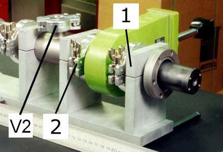
- loosen the support (1) (the one before the valve VAT, see Fig.3) using the allen wrench;
- loosen the clamp (2) after the VAT, as seen in Fig.3;
- remove the probe;
- in order to rough pump the valve, put the special KF adapter on the VAT valve using the same clamp and o-ring that fixed the probe. These adapters can be found in the “vacuum spare parts” box in the tomography cabinet (2nd floor). SXR1 and SXR4 valves will be connected together (two adapters and one tube), SXR3 will have its own adapter. The tube should be connected to one V1 (or V2) valve, the remaining V1,V2 valves should be left closed;
- when all needed probes have been disconnected and the KF adapters attached to the valves, the V1 (or V2) valves connected to the VAT roughing line should be opened. Rough pressure will increase to several mTorr and will decrease slowly. In 45 minutes it should be ok
|
| Mounting the manipulator on MST |
|
When all the operations of substitution, modification etc. have been executed, the diagnostic(s) can be mounted on the vessel in the following way (repeat actions 4…10 for each manipulator):
- ask permission to the run coordinator of the day, and to the coordinators of the remaining days of the week, to install the probe on MST;
- annotate both MST and roughing system pressure;
- close the V1 (or V2) valves (see Fig.2) used to rough pump the VAT valves, and disconnect the KF adapters from the VAT valves. The remaining V1,V2 valves should be already closed;
- put the instrument in the same porthole, with the same orientation (use the signs on the vessel); close, without tightening, the clamp (2) and the support (1) (see Fig.3);
- rotate the instrument around its axis until it is in the same position as before (help with the signs on the vessel);
- tighten the support (1) and AFTER THAT tighten the clamp (2) (see Fig.3) (the alignment of the diagnostic is made with the rigid supports, not with the clamp!);
- connect the electrical cables on the flange;
- connect the tubes of the roughing vacuum system;
- open the valves of the roughing line. First the V1 valve (Fig.2), and the roughing line should increase and then decrease quickly. When roughing pressure is around 13 mTorr open the second valve, V2 (Fig.2). Pressure will increase to several mTorr and will decrease slowly; it will take up to two hours to get to 10 mTorr;
- after a few hours, if there are no objections from the other, or (better) the following day, if the MST vacuum is ok it is possible to open the VAT and then close (not completely). Pressure should not change;
- for probe SXR1, use the white spacer (see Fig.1) and put it horizontally.
Remember to annotate the installation of the probe and the opening of the VAT valve in the MST vacuum logbook, along with the date, time, and pressures.
If the probes need to be inserted then follow the checklist for Inserting/Extracting the probe.
|
| Inserting/extracting the probe |
At the beginning of the session the SXR1, SXR3 and SXR4 probes (located at 300T, 75,315 and 45P) should be inserted in their measurement positions, while at the end of the day the same probes should be extracted, to protect the Be filters.
List of actions:
Insertion (the probe is already connected to MST)
- the V1 valve (Fig.1) of the roughing line should be already open and must be left open;
- the V2 valve (Fig.1) of the roughing line should be already closed and must be left closed;
- open and secure the VAT valve. MST pressure should remain the same;
- for SXR1, remove the white plastic spacer (Fig.2) and put it somewhere on the probe;
- insert the probe in measure position, controlling also the alignment of the probe (that is the alignment of the plane of the lines of sight; usually this plane is a poloidal section of the torus, and the orientation is called "poloidal"). For SXR1 use the 3/4’ speed handle, for SXR3 and 4 use one the two “orange” speed handle;
- insertion values are 124 mm for SXR1 and 147 mm for SXR3 and SXR4 (knife edge side);
- check that all power supplies of amplifiers and iso-amps are on;
- set the gains (transimpedance and iso-amp gains). Possible setting are 1x, 2x, 5x for iso-amplifiers and 10^5, 10^6, 10^7 for transimpedance amplifiers;
- check the pulsefile: from mstdata@aurora type fd, then idl and then sxrtomo_set_acq, <keywords>, where <keywords> can be /on to switch on the data acquisition of all channels, /off to set off the data acquisition for all channels or /sxr2 to switch on only the data acquisition of the SXR2 channels;
- set the parameters in the pulsefile, using the IDL program sxr_mst_write_par Please follow the instructions in the document "SXR TOMOGRAPHY Handy Book".
Extraction (without removing the diagnostic)
- extract the probe to the end. For SXR1 use the 3/4’ speed handle, for SXR3 and 4 use one the two “orange” speed handle;
- in order to close (crack) the VAT valve the SXR1 probe should be further extracted 4-5 cm, use the white spacer (see Fig.2);
- annotate the MST and roughing line pressure (usual values are 1x10⁻⁶ Torr and 10 mTorr, resp.);
- close (not completely) and secure the VAT valves; pressure should not change;
- the V1 valve (Fig.1) should be already open. Leave it open;
- the V2 valve (Fig.1) should be already closed. Leave it closed;
- check that all power supplies of amplifiers and iso-amps are on;
- check the pulsefile: from mstdata@aurora type fd, then idl and then sxrtomo_set_acq, <keywords>, where <keywords> can be /on to switch on the data acquisition of all channels, /off to set off the data acquisition for all channels or /sxr2 to switch on only the data acquisition of the SXR2 channels;
- set the parameters in the pulsefile, using the IDL program sxr_mst_write_par Please follow the instructions in the document "SXR TOMOGRAPHY Handy Book".
Anytime the gains are changed these parameters should be written in the pulsefile, using the IDL program sxr_mst_write_par. Please follow the instructions in the document "SXR TOMOGRAPHY Handy Book".
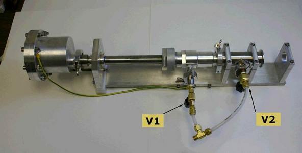 Fig.1
Fig.1
|
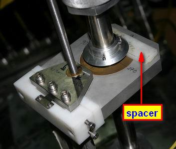 Fig.2
Fig.2
|
|
| Removing/replacing the beryllium filter or the pinhole |
|
To replace/remove the beryllium filter or the pinhole foil just follow the instructions in this page.
|
| Replacing the IRD detector |
|
To replace the IRD detector the diagnostic should be extracted (see the exact procedure here). List of actions:
- put the diagnostic on a bench horizontally and push on the back (flange) to extract the aluminium probe, as in this picture;
- remove the four screws in front of the probe to open it, and the detector can be seen on its Teflon socket:
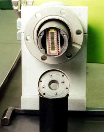 ; ;
- remove the array taking the chip by its short edges. To perform this operation a special tool should be used: it is a small pliers/nipper with bent nose that can be found in the carton box with all the metric tools (this box, and other equipment, is inside a cabinet in front of Den Hartog's office):
- put the array in its plastic box (these boxes can be found in another carton box in the cabinet; it can be recognized by a label 'IRD' on one of its sides);
- place the new array of detectors in the socket, using the same pliers/nipper, or a bigger one: first put the array in its position and then push on the short edges, alternatively, until the pins of the chip are completely inserted;
- before closing the probe, check with a meter that all the diodes are working fine: select 'check diode' on the meter and measure the lemo feedthroughs of the flange; check also that all the diodes are grounded together (checking that all the feedthrough grounds are connected together);
- if everything is fine then close the probe by placing the front top and fixing it with the 4 screws;
- re-install the diagnostic on MST following the procedure described here.
|
| SXR2 (fixed version) installation |
|
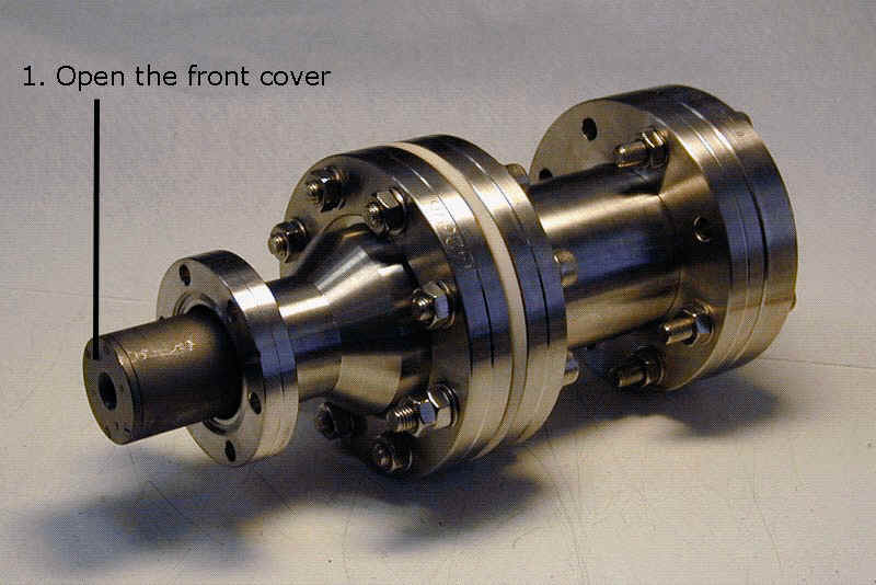
To install the SXR2 probe you should perform a simple check of the orientation. First open the front cover (there are 4 screws). Be careful with the cover because on the back there is the curved Be filter.
Put the probe on a table in vertical position and look at the detector.
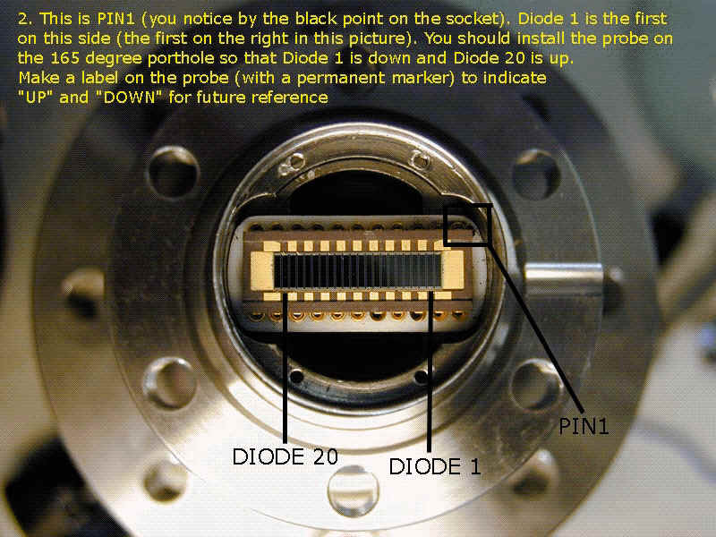
Find the black point on the socket: this is PIN1; you can then find Diode 1 and 20. Make a label (with a black permanent marker) and write "UP" on the probe on the side of Diode 20, and write "DOWN" on the side of Diode 1. This way the line of sight of Diode 1 will point up and that of Diode 20 will point down.
After that close the probe with the front cover; the diagnostic is ready to be installed.
|